Our Cisco APs are multi talents, they can operate in several different modes. This makes these APs very flexible in use.
Let’s have a look an the modes available (26.01.2019):
- Local -> Transfers data and monitors the air space, the results are sent to the WLC and with this information the AP is able to made decisions such as flexible channel assignment or get informations about other APs and networks nearby.
- Monitor -> Only monitoring, like described under „local“
- Sniffer -> Acts like port mirroring, all frames are redirected to a specified IP-address.
- Rogue Detector -> …
- Bridge -> Behind this hides the „Mesh“. This mode is quite cool. You can set up a Root-Access-Point (RAP) with a wired connection, then you can mount more APs, on light poles for example, within the cell range of the RAP as Mesh-Access-Points (MAP) and these MAP’s are building are wireless-link to the RAP to gain access to the WLC and to serve clients with data from the DS.
- SE-Connect -> …
- OEAP -> Office Extend AP is AP that employees can use at home for home-office or so on. The AP connects over the internet to the WLC in HQ and you can connect to your corporate SSID and can access all resources like in the office. BUT a great feature is that this mode also offers Guest-SSIDs for your family and friends. If you connect to this SSID your traffic is dropped into the internet like a wired client in your home network.
- H-REAP/Flex Connect -> Helps to serve locally switched WLAN with central management. The WLC operates in the HQ and if there are branch offices they can use FlexConnect to drop the traffic in the LAN. In „local“-mode the AP else would tunnel the traffic to the WLC and then back to the resource in the branch with double penetrating the WAN-link (up and down)
Roaming
There are two types of roaming:
>Layer-2 Roaming:
Let’s imagine a customer with a huge space, needed to be served by WLAN in every corner. So it can happen that you need more than one WLC to support the load. Another situation can be that the customer itself bought some refurbished WLCs, each licensed for 15 APs and need 30APs for VoIP without any drops.
Regardless which scenario we like to pick, roaming takes care that our WLAN-device always moves to the next AP while we walk around the area. For the client this is a transparent process and without a drop in the connection.
But now we want to roam from AP-A-1 (located on WLC#A) to AP-B-1 (located on WLC#B) without any kind a dropped frames. To make this work, both controllers need to know each other must exchange their status.
The first step is to make sure that:
>only CAPWAP or LWAP is used (only one)
>both WLC sw-version are compatible
>both are using the same virtual IP (1.1.1.1)
> make sure the WLAN is configured on both WLCs identically
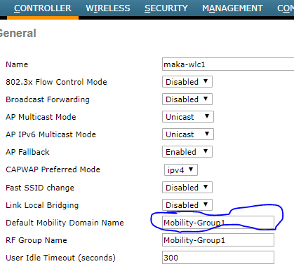
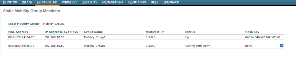
Next we need to set the name of the MOBILITY-GROUP.
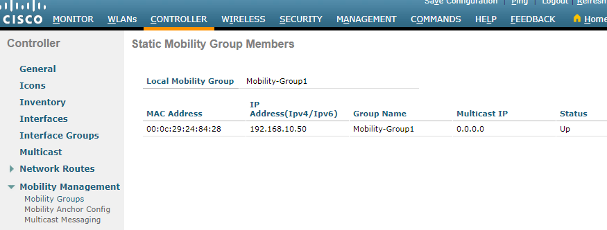
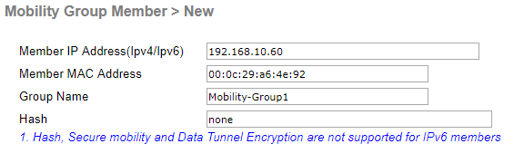
Now let’s marry controller one and two so that they know each other to make this wonder work:

>Layer-3 Roaming
NOTE: Layer-2 roaming is used if the WLCs, used in the mobility-group, can all supply access to the network the SSID is associated with. The traffic to the DS move from one WLC to the other.
If the WLCs are sitting in different networks and the second WLC can not provides access to the network the SSID the client needs, because the required VLAN is not accessible in this part of the network, the traffic flows in a tunnel. The WLC the client originally authenticated with is the anchor WLC and the bad WLC, with no direct access to the required network, is the foreign WLC. The traffics flows from the foreign WLC to the anchor WLC and than into the network, also backwards. This is invisibel for the DS. This the symmetric version of Layer-3 roaming.
There is also a version a asymmetric roaming. The difference is that the foreign WLC drops out the traffic from the client and the answers are sent to the anchor WLC and then tunneled to the foreign WLC and then to the AP, serving the client.
Another sub-type is the „mobility-anchor“, this mode can be used if one controller should handle everything for a SSID, for example a guest-network. No other controllers process this traffic, authentication, etc. they just forward to the mobility-anchor. This is done in a tunnel.
The last, but for me not often seen, function or mode is the „Static Address Tunneling“. It’s based on the same topics I described before. If there is an SSID, served by two WLCs and a client with a static IP, let’s say 192.168.10.10.
The first WLC serves out the 192.168.10.0/24 and the 2nd 192.168.20.0/24. Now the client with the static IP tries to authenticate initially at the 2nd WLC, because there APs are nearby. Normally this won’t work – but as the WLCs are in a Mobility-Group they know each other. So the 2nd WLC sees that this network, the client has configured at it’s WiFi-card, is accessible via the 1st WLC and so it tunnels the traffic to the 1st WLC.