WIFUND –18– 802.1x und EAP

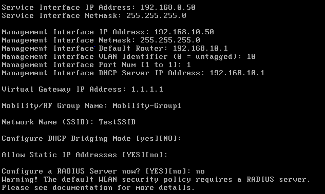
Kommen wir nun zum Thema Sicherheit und zu Technologien die wir auch in Unternehmensnetzwerken einsetzen können.

Die entspannte Basis von 802.1x ist das die Standard Antwort immer NEIN ist.
Recht einfach oder? Aber was wenn nun sich doch mal ein Unternehmens-Laptop mit dem WLAN verbinden möchte? Fangen wir etwas weiter vorne an.

801.1x ist ähnlich eines WLCs eine Verlagerung von Intelligenz. Statt das ein PSK auf einem Access-Point oder einem WLC hinterlegt wird spielt hier ein zentraler Server die wichtige Rolle. Der AAA-Server, Authentication, Authorization and Accounting, sorgt an zentraler Stelle, wie der WLC für die WLAN-Infrastruktur, dafür das Benutzeranmeldungen geprüft und ggf. positiv bestätigt werden.

Jeder Teilnehmer in diesem Prozess bekommt eine Rolle, unser Laptop ist der Supplicant, der Access-Point ist der Authenticator und der AAA-Server nimmt die Rolle des Authentication-Server ein.

In meinen einfachen Worten gesagt: Client will ins WLAN, AP sagt „Erst sagst du mir wer du bist, ich brauche deinen Benutzernamen und dein Passwort“.
Darauf der Client „Okay, mein Benutzername ist „Boss“ und mein Passwort „IRule!“.
Der AP, aka der WLC da wir unsere APs ja als Lightweight betreiben, schickt diese Daten an den für das WLAN hinterlegten AAA-Server und warte dessen Antwort ab.
Dieses ist simpel: JA oder NEIN. Der AAA-Server schaut inzwischen in seiner Datenbank ob der diese Kombination von Username und Password kennt und ob diese berechtigt ist am WLAN teilzunehmen.
Anschließend erhält der WLC z. B. das „JA“ vom AAA-Server und lässt den Client am WLAN teilnehmen. Cool oder?

Als AAA-Server gibt es von Cisco z. B. den ACS oder die ISE, Identity-Service-Engine,
es gibt aber auch viele freie Versionen. Die „Sprache“ die benutzt wird um diese Anmeldung am WLAN durchzuführen ist RADIUS.

Das Framework, also welche Methoden der Anmeldung es gibt sind im EAP, Extensible Authentication Protocol, geregelt. Es gibt hier vier wichtige EAP Varainten:

LEAP = Lightweight EAP
Einfache Variante wobei sich Supplicant und AAA gegenseitig validieren damit der Client seine Daten nicht einen Bösewicht statt dem AAA sendet.

FAST = Flexible Authentication via Secure Tunneling
Hier wird ein Tunnel zwischen dem supplicant und dem AAA aufgebaut und die Daten mittels PAC, Protected Access Credentials, versendet. Es benötigt keine digitalen Zertifikate.


PEAP = Protected EAP
Der AAA-Server präsentiert dem Client sein Zertifikat, der Client prüft dessen Gültigkeit und Authentifiziert sich selbst durch Username und Password.

EAP-TLS = EAP Transport-Layer-Security
Ähnlich PEAP nur das hier auch der Client ein Zertifikat vorweisen muss damit sich beide Systeme gegenseitig vertrauen.

Wie funktioniert das mit den Zertifikaten?
Platt gesagt, recht einfach. Unser Personalausweis ist sin solches Zertifikat.
Dieser wurde von einer vertrauensvollen Stelle ausgefertigt und unterschrieben, bei dieser kann man jederzeit die Gültigkeit z. B. anfragen. Mit diesem Dokument können wir uns z. B. gegenüber der Polizei authentifizieren.
In der digitalen Welt funktioniert das ähnlich, es gibt diverse öffentliche CAs, Certificate Authorities, oder auch PKI, Public Key Infrastructure, die für z. B. eine Bank, die Online-Banking anbieten möchte, ausstellt. Verbinden wir uns via HTTPS mit unserer Bank sollte das in ungefähr so aussehen:

Unser Browser vertraut dem Zertifikat und stuft die Webseite als sicher ein.
Dies hat er getan in dem er die im Zertifikat enthaltene Signatur geprüft hat, quasi die Unterschrift des Ausstellers des Zertifikats. Damit die Verbindung nun auch wirklich sicher ist soll die Kommunikation verschlüsselt werden, dieses geschieht mithilfe eines Public-Keys den jeder erhält der die Internetseite öffnet. Nun kann unser Browser Daten mithilfe dieses Keys verschlüsseln und nur die Gegenseite, also hier die Bank, hat den sogenannten Private-Key, der es erlaubt die Daten wieder zu entschlüsseln.
???Damit die Sache rund wird, schickt auch unser Browser einen Public-Key an die Bank so das die Kommunikation in beide Richtungen verschlüsselt und damit sicher ist.????
Wir selbst authentifizieren uns meist per User/Password an so einer Webseite.

WIFUND –16– Converting AP software

There are to different modes an AP in general can operate:
– autonomous aka standalone
– lightweight aka WLC controlled

The good news are, we don’t switching these modes every day, but it’s good to know how to do this if you for example want to get a bunch of autonomous APs to move to a WLC.

To switch between these modes we’ve to replace the image-file of the AP.
To bootstrap an AP it’s first important to know which images is needed. You can use the following reminder to differentiate the to images-files:
lw= ….k9w8 (<-spell like weight….lightweight^^)
autonomous = ….k9w7

To transfer the files to the AP we must provide a TFTP-server. This TFTP we can run on our laptop. I mostly uses this one:

http://tftpd32.jounin.net

Now we need the images-files. These can be downloaded at cisco.com, login with your user/pass, navigate to downloads/support and search for the AP you want to update.

To let the AP automatically download the new software, we must rename the file:
cXXXX-k9w7-tar.default (for the autonomous software). XXXX=AP-type.

Next we must give our laptop (which runs the TFTP-server) a IP adress, so that the AP can reach the TFTP-server. Let’s take 10.0.0.2 and now we unplug the AP.

Then hold down the mode button of the AP (to set it to image recovery mode) and apply power, the AP will boot up with the IP 10.0.0.1 and sends out a TFTP broadcast and looking for the file renamed above. Please release the mode button after ~20 seconds after the LED went red.

Next the AP loads the file, extract it to flash, reboots and KABOOOMMMMM….done.
Same method for the way back to CAPWAP, rename the file with k9w8.

Now, with our autonomous AP you’ll see that the CLI is quite different in relation to a CAPWAP-AP. It feels like on a Cisco router or switch…..like it 🙂

To configure this AP we can use the console or the browser.
The login at the browser has little crazy, because you must only enter the password if you login the first time. So only enter „Cisco“ as password and leave the username blank.

WIFUND – 15 – AP Modes and Roaming (DRAFT!)

Our Cisco APs are multi talents, they can operate in several different modes. This makes these APs very flexible in use.

Let’s have a look an the modes available (26.01.2019):

  • Local -> Transfers data and monitors the air space, the results are sent to the WLC and with this information the AP is able to made decisions such as flexible channel assignment or get informations about other APs and networks nearby.
  • Monitor -> Only monitoring, like described under „local“
  • Sniffer -> Acts like port mirroring, all frames are redirected to a specified IP-address.
  • Rogue Detector -> …
  • Bridge -> Behind this hides the „Mesh“. This mode is quite cool. You can set up a Root-Access-Point (RAP) with a wired connection, then you can mount more APs, on light poles for example, within the cell range of the RAP as Mesh-Access-Points (MAP) and these MAP’s are building are wireless-link to the RAP to gain access to the WLC and to serve clients with data from the DS.
  • SE-Connect -> …
  • OEAP -> Office Extend AP is AP that employees can use at home for home-office or so on. The AP connects over the internet to the WLC in HQ and you can connect to your corporate SSID and can access all resources like in the office. BUT a great feature is that this mode also offers Guest-SSIDs for your family and friends. If you connect to this SSID your traffic is dropped into the internet like a wired client in your home network.
  • H-REAP/Flex Connect -> Helps to serve locally switched WLAN with central management. The WLC operates in the HQ and if there are branch offices they can use FlexConnect to drop the traffic in the LAN. In „local“-mode the AP else would tunnel the traffic to the WLC and then back to the resource in the branch with double penetrating the WAN-link (up and down)

Roaming

There are two types of roaming:
>Layer-2 Roaming:
Let’s imagine a customer with a huge space, needed to be served by WLAN in every corner. So it can happen that you need more than one WLC to support the load. Another situation can be that the customer itself bought some refurbished WLCs, each licensed for 15 APs and need 30APs for VoIP without any drops.

Regardless which scenario we like to pick, roaming takes care that our WLAN-device always moves to the next AP while we walk around the area. For the client this is a transparent process and without a drop in the connection.

But now we want to roam from AP-A-1 (located on WLC#A) to AP-B-1 (located on WLC#B) without any kind a dropped frames. To make this work, both controllers need to know each other must exchange their status.
The first step is to make sure that:
>only CAPWAP or LWAP is used (only one)
>both WLC sw-version are compatible
>both are using the same virtual IP (1.1.1.1)
> make sure the WLAN is configured on both WLCs identically
Next we need to set the name of the MOBILITY-GROUP.

The mobility domain name is the name of the group the controller belongs to.

Now let’s marry controller one and two so that they know each other to make this wonder work:

In the Mobility Groups we first see only our current WLC. On the second WLC we’ll see the same for, both are still lonely.
In the upper right we click „NEW“
Then we add the neighbor WLC, with it’s IP-address (not the service IP!) and the MAC-Address. The MAC can simply be copied from the second WLCs “ Static Mobility Group Members “ overview.
Then it should look something like this, but here the path’s are down (connection problem in my case – try the blue arrow on the right of the line, it allows to ping the neighboring WLC). There is also the mping (to check the management path) and the eping (to check the data path) command.


>Layer-3 Roaming
NOTE: Layer-2 roaming is used if the WLCs, used in the mobility-group, can all supply access to the network the SSID is associated with. The traffic to the DS move from one WLC to the other.
If the WLCs are sitting in different networks and the second WLC can not provides access to the network the SSID the client needs, because the required VLAN is not accessible in this part of the network, the traffic flows in a tunnel. The WLC the client originally authenticated with is the anchor WLC and the bad WLC, with no direct access to the required network, is the foreign WLC. The traffics flows from the foreign WLC to the anchor WLC and than into the network, also backwards. This is invisibel for the DS. This the symmetric version of Layer-3 roaming.
There is also a version a asymmetric roaming. The difference is that the foreign WLC drops out the traffic from the client and the answers are sent to the anchor WLC and then tunneled to the foreign WLC and then to the AP, serving the client.

Another sub-type is the „mobility-anchor“, this mode can be used if one controller should handle everything for a SSID, for example a guest-network. No other controllers process this traffic, authentication, etc. they just forward to the mobility-anchor. This is done in a tunnel.

The last, but for me not often seen, function or mode is the „Static Address Tunneling“. It’s based on the same topics I described before. If there is an SSID, served by two WLCs and a client with a static IP, let’s say 192.168.10.10.
The first WLC serves out the 192.168.10.0/24 and the 2nd 192.168.20.0/24. Now the client with the static IP tries to authenticate initially at the 2nd WLC, because there APs are nearby. Normally this won’t work – but as the WLCs are in a Mobility-Group they know each other. So the 2nd WLC sees that this network, the client has configured at it’s WiFi-card, is accessible via the 1st WLC and so it tunnels the traffic to the 1st WLC.

WIFUND –14– Connect the APs

Our APs are very intelligent devices, when they boot up they’re shouting out a broadcast message, asking for a controller and stores this into flash for further usage. This works fine until we put the WLC and the APs in different subnets. For this situation we can set up a DHCP-server and configure the option 53, also we can configure a DNS-server to respond to CISCO-CAPWAP-CONTROLLER with the IP of the WLC. Summarized, there are 4 ways to connect the AP.

I hope this is going without saying: Powering the AP via PoE or a power-injector, maybe a power-supply.

The next step is to elect the WLC the AP want to connect with, if they’re multiple responses. If the AP is already connected, we can configure a primary, secondary and tertiary controller for each AP. So if one controller fails or the AP could not find the first one during the boot process it connects to the next one.
The next in line is to brand an AP to connect with a WLC the is the „MASTER CONTROLLER MODE „. This mode automatically writes the WLC’s IP into the APs config.

The last way if the AP found several WLCs is the to choose by the load of the WLC’s. The load is measured by the connected APs and the license applied. 10 APs licensed, 8 connected, 80% load.

The initial get to know between the WLC and AP runs over the control-channel, at port 5246 UDP at the controller. The is done with DTLS, Datagram Transport Layer Security.
They’re exchange their certificates, first the WLC to AP and the AP to WLC.
The DTLS traffic then runs encrypted, farther via UDP port 5246. The client data is transfered via UDP 5247 and is not encrypted by default!


What I found in the latest WLC version is very extreme, but it’s prescribed by law in some country’s 😉

WIFUND – 13 – Deploying a WLAN

The vWLC is up and running and it’s time to set up the first WLAN.
There is a simple list I follow and like everywhere is good preparation a way.
I go more in detail later….:

  1. What VLAN your WLAN should bridge to? VLAN = 33
  2. Get the subnet and a free IP out of this subnet for the virtual interface? 172.16.33.0/24 172.16.33.3
  3. Is a DHCP usable for this subnet? Yes, 172.16.33.1
  4. Is the air space free to transmit in the 2,4GHz or 5GHz band (site survey) = No, we use 5GHz band
  5. Get a minimum of 1 AP up and running
  6. Create a virtual interface on the WLC
  7. Create a virtual interface with IP 172.16.33.3, a 802.1q tag of 33 and a DHCP with the IP 172.16.33.1
  8. Create a WLAN with a name of our choice and refer/link it to the VI

WIFUND –12– Deploying vWLC

And now…let’s do some practical work.
To play with a WLC, in our case the vWLC we need the OVA-file to deploy the vWLC into VMWare Workstation or a ESXi/vSphere environment.
I download it’s from this landing page: https://www.cisco.com/c/en/us/support/wireless/virtual-wireless-controller/tsd-products-support-series-home.html

Now, before we start let’s check what we want to do and our network topology:

XXXXX INSERT IMAGE XXXXX

So let’s do it step by step:

Please do it 🙂 , my cup of coffee was empty and meanwhile the vWLC stuck in this :(. Restart….
It then looks like this 😉

The commands in the brackets are the presets, with enter you can acknowledge them are type „no“ and YES we like to cancel the autoinstall. Next the hostname is wanted, but do not be confused, the lines have slipped.
Choose your name for login into the WLC
…and set a password. Don’t use „Cisco“ and it need upper and lower case including digits. For this lab I use „Password123“
The Service-Interface is the dedicated interface only accessible for us as administrator, the management interface is also needed for the APs to connect and for the WLC to later drop out the traffic from the wireless clients. The virtual gateway IP is an internal address, needed if we want to roam between APs that are located on different WLCs, therefore the Mobility Group is also needed.
Then enter the SSID of our first wireless network. We dont‘ want to bridge DHCP, allow static IPs at our clients and don’t need a RADIUS right now.
Then we need the country code, this is important because as we learned earlier, there are regulations and you must use the frequencys that are allowed in your country.
Next we enable the use of the different networks(/b/a/g) and use Auto-RF for optimization..
As you see, my NTP is not working, so I configure the time manually.
No IPv6 at this time and we’re DONE.


After reloading you see something like this.
Now you can connect to the server-port IP via HTTPS and login with the user/pass you configured before.
Now you’re at the „new“ monitoring homepage of the fresh deployed vWLC. Somewhere in WLC version 7.X it’s getting accessible via a FUS-update. This page helps you to get an fast overview of your network and the status. To get into the normal configuration mode you need to click „Advanced“ in the upper right of the screen.
Finish. Your’re done 🙂
The evaluation license is automatically active and running.

In order to get your APs automatically registered at the WLC you could run a DHCP in the APs subnet with the DHCP-option 43 including the IP-address of the WLC data-port.

WIFUND –11– WLC – Overview

Okay, the basics are in mind and we’re starting to deploy our WLC.
But, stop, wait and minute….- we forget to have a look on the different types of Cisco WLC and their deployment options.

As I began to deploy and manage wireless networks there where only a few controllers and only physical machines. I started with the 2100er series, later the 2500er series and today (01.2019) we’re at the 3500er series for the small to midsize controllers. Also in the past there where a lot of modules for switches and routers – they’re gone :).

The WLC is simply a computer with interfaces and a special operating system, end of story. It’s like with very other vendor: The appliances are physical devices and designed and optimized to do only „WLAN“. The older cards/modules are special processor boards to do the same job but you can put them into a big modular router. The virtual WLC, or vWLC, is a very popular version of doing WLAN – but here you’re instructed to only use H-REAP, later more. There are switches with integrated WLC-functionality, activated via license.
There are so many different versions of appliances, I don’t know if we need them all 😀 , but they are there.

The history of the SMB controllers.

Below is screenshot of the Cisco Homepage, please check out the link to see all the different types of appliances. In fact they differentiate through the interfaces, CPU power and last but not least – the maximum APs they can handle.

https://www.cisco.com/c/en/us/products/wireless/wireless-lan-controller/product-comparison.html

A difference between the WLC types, as I said before, is the amount and types of interfaces. There:
ethernet interfaces – we can configure them as trunk to access the DS, separate traffic physically, bind them to get more throughput and so on.
dedicated mgmt/OoB – these ports are only used to mange the WLC, we also can access the management via the other ethernet-ports if we like to, but this port is intend for use in a separate mgmt-network (also physically divided from the production network).
service-port/console – the normal console port you know from Cisco

WIFUND – 10 – VLAN mapping to SSID

Okay, it getting more and more hot 🙂 .
Know we know the fundamental concept’s but how to use it in the real world?

If you and I have a customer, which wants a WiFi network for the engineering- and the marketing-division, which both have their own VLANs, we have several way’s to get this job done, but only one way the make this great. Sure, we could install two autonomous APs, each for one SSID – sounds as bad as is. The question is: How to get AP sending out two SSIDs which each connection to different VLANs in the network?

Trunking or 802.1q is the technique we need. Everyone who is familiar with networking should know this but I can give a short breakout:
VLANs  aka virtual LAN’s is the way to virtually split up a network switch.
Why do we need this? In a company with many departments there are many regulations, for example that the network for the engineering and the sales guys is separated from each other. To do this in an oooooooold fashion, we buy two switches, one for the engineering and one for the sales guys. This is connected with a lot of trouble, for example you know must buy and mange two devices.
VLANs allow to do this separation within the switch. Imagine a small 8-port switch, we can configure port 1-4 for the engineering and 5-8 for the lovely sales guys.

So back to topic, back to 801.1q. Now our fantasy company rents’s the second floor in the building, a new switch for this is purchased and our sales- and eng-guys are now distributed on two floors and connected to. But how should sales guy1 send data to sales guy2 if they are each on different floors? Okay, first we need to connect the switches. But as we configured the VLANs, how should the switch on floor2 know to which ports , the traffic received, should forwarded to?
The solution is simple and there a many mnemonic’s to get this in mind, this is my:
On the ports we connect switch1 and switch2 must be configured to do 801.1q tagging. This tagging ensures that the receiving switch know for which VLAN the packet was intended to. It’s like a little pricetag attached to every packet leaving a trunk-port.

So back from out excursion to VLANs…:
To get two SSIDs, each serving a different VLAN, out of one AP we need MBSSID (multiple base service set identifier). Because our APs are connected via a CAPWAP with the WLC and they don’t need to process the wireless traffic, because this data is send to the AP via the CAPWAP data stream, we configure the ports on the switch for the APs as access-ports. This means this port is only member of one VLAN. This could be a special VLAN where we want to put our APs in or maybe the same as our WLC resides in, the only important thing to keep in mind, the APs must reach the WLC. As the WLC forwards the packets to the different VLANs, it needs the one who get’s a trunk-port. The spanning-tree portfast option uses the newer version of the SPT-protocol and avoid the 30sec delay when connect devices. The last screenshot shows the warning of SPT-portfast, which is normal.

Also you can set the switch to trust DSCP-markings. These markings are used for Quality of Service (QoS). For example voice-traffic from a wireless phone. It’s only useful if these markings are used within your network.

In fact, you will connect the following to static access-ports:
– Lightweight-Access-Points

And this to trunk-ports:
– WLC
– Autonomous APs
– H-REAP APs

H-REAP???
Hybrid-Remote-Edge-Access-Point, is a sub-form of an AP that is processing the data-traffic itself, but farther get’s managed by the WLC with all it’s benefits.
But why I should use H-REAP?
It’s mostly used if your customers owns several branch offices which also needs WiFi.
For this you can centrally deploy a WLC in the headquarter and connect the APs in the branch offices to it. The goal of this design is that the traffic doesn’t flow through the WLC and this will no affect the WAN-link between HQ and the branch, because the APs processing the traffic itself.

WIFUND -9- WLC and AP concepts

So here we are, our WLC is up and running, also some APs and a lot of hungry clients, waiting for a connection.

The first we need to talk about is SPLIT MAC. This concept means that in a controller based WiFi-network a lot of tasks are moved from the AP to the controller.
That’s great because the controller makes it muuuuuuch easier for us, no one wants to configure 100 APs one by one.

In fact the WLC takes over the complete processing of the packets, dis-/association, authorithation, policys, frequency management and so on. The AP, on the other hand, concentrated at the radio functionality and also:
– Any real time traffic (sending beacons, probes and ack’s)
– Manage the RTS/CTS

Do you know old telephony systems with the legacy DECT-radios which are directly connected to a line-card of the PBX (for example an Siemens HiPath and the BS4 radios)? Virtually there is affinity as the WLC it does.
Because the WLC manages the AP and also need the data-traffic for processing there are two types of virtual cables aka tunnels, between the AP and the WLC. Please do not beat me 🙂 , it’s the way I best save this into my brain.
In old telephony systems the DECT-radios are directly connected to the PBX and the are a part of this, like router at home with buildin WiFi – it’s also part of the device.

But our AP is a very happy standalone device, with it’s on IP and config. The WLC is so sad, because he want to serve you with WiFi, but without any radio, no way.
So let’s connect the AP to the WLC like an old DECT-radio to a PBX:
First we need a cable to control the AP, tell it what to do, especially send the config or also the AP send back things like which other APs it see’s. That’s our control cable. Next we need a cable for the data-flow of our wireless-clients. Because not the AP should process this, it’s a job for the sad WLC to make him more happier. This is the second cable, the data-cable. STOP!!! But hey, we don’t need a dedicated cable or so on, because the AP and the WLC are talking via IP, we use the IP-network to connect them.
This is done with CAPWAP (Control and Provisioning of Wireless Access Points).
But whats this? In my brain I saved it up as a „tunnel“ between the WLC and the AP, like a VPN tunnel, it’s also encapsulated.

WIFUND -8- WLAN Disrupters

Let’s hold this chapter short.
As we’re sending and receiving signals in the 2,4GHz and 5GHz band, there also other devices that sending there signals out here and these aren’t wifi-devices ;).

First there is WiMax. It’s used as an alternative to DSL to serve household over the air. WiMax is a last-mile wireless broadband access operating amongst other things at 2-11GHz.
https://en.wikipedia.org/wiki/WiMAX

The Internet-of-Things, some say a great invention other say it’s hell.
ZigBee operates in the 2,4GHz band and it’s most popular application is Phillips HUE.
It’s used to operate lamps, meters and many other things you need for your connected house. It is not a rarity to find a household with >20 devices connected.
https://en.wikipedia.org/wiki/Zigbee

Bluetooth, everybody know it – everybody use it. It only sends in a small cell but if there are many devices it can generate a disturbing noise for our WiFi. It also operates in the 2,4Hz band.
https://en.wikipedia.org/wiki/Bluetooth

There are some more devices that can disturb our Wifi. Every device that operates in the same unlicensed frequency space can do that. Microwave oven, wireless cameras, wireless gaming controllers, DECT telephones, motion detectors,….a long list you see.

The microwave oven may only be a problem during lunch time, where everybody heats up there meal. Because it’s generates a noise that can affect the signal quality, end up missing packets or shuttering phone calls with a WiFi-Phone.

Fluorescent lights can have impact because they’re changing the way a signal get’s reflected. It’s not the frequency they’re operating at, it’s the fact that they’re operate at 50-60Hz, very slow. If the signal is hitting the light if it’s charged the signal and sometimes if it’s not charged and this is changing the reflection.

And great news for me and maybe for you too:
WE’RE DONE WITH THE PHYSICS…..let’s start with the WLC!