Welcome to the world of frames. So what the hell is a frame, especially a wireless frame. Give me a try, a frame is located at layer 2 of the OSI model. Do not muddle it up with a packet, packets are located at layer 3! The data link layer (2) is responsible for a reliable transportation of data between two devices.
In wireless networks, frames are so important because they give us information about what wireless networks are nearby, they’re control when it’s save to send data – because it’s a shared medium. Carrier Sense Multiple Access with Collision Avoidance or CSMA/CA is the technique which controls the sharing of the wireless space.
There are several frame types: Management: Beacons, Probes, Authentication and Association Control: RTS, CTS, ACK Data: the data – payload
So, how get the signal out of our AP? Of course, we use an antenna :).
Before we talked about signals, mW and dB. This is the time we transform this electrical signal into electromagnetic waves – which can be transmitted over the air.
Imagine a customer wants WiFi in their office and we have the pleasure to implement this. Our client gives us a plan so that we can get an overview of his office.
Before we start to position APs we need to know how the electromagnetic waves getting radiated through the building. To do this each antenna has it’s own characteristic – but they’re sorted into two major categories:
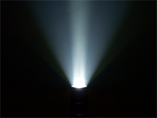
Unidirectional antenna: Like the beam from a flashlight, heading into a specific direction and gets wider with distance:
Omidirectional antenna: Imagine a normal light Bulb without lampshade, the light is spread evenly into the room:
But this is only for orientation! In fact, every antenna has it’s own properties. For us, as the ongoing WiFi experts, the manufacturer are supplying two types of drawings for their antennas to let us know how they radiate. The H-plane, azimut-plane is the top view. We’re looking down on the plan and it shows how the signal distributes to the horizon. The other view is the E-plane, this is the side view. With this two drawings you get a feeling how this antenna works and if it’s useful for your project. Later more…
Now back to numbers 🙂 … To measure the effective power our AP sends out is the EIRP (Effective Isotropic Radiated Power). It’s calculated with the dBm that our AP generates PLUS the antenna gain (it’s no gain like a receiver) MINUS cable loss. For instance 28dBm AP + 6dBi antenna = 34dBm of EIRP. Almost forgottten: The antenna gain is dBi, where is „i“ stands for isotropic.
Diversity. Instead of listing with only one antenna or one „ear“ to the Wifi – the AP has two or more separate antennas and can selected the best to receive the signal.
…DIPOLE REFERENCE TO DO…
The antennas connectors are mostly proprietary, not worth mentioning general connector out there. But this is good to make the AP and the antenna a winning team, without exceed the allowed EIRP in your country.
For outdoor antennas it’s best practice to use a lightning arrester!
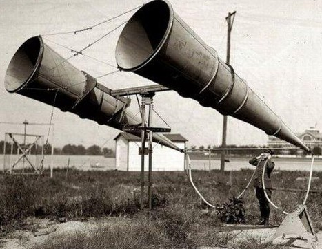
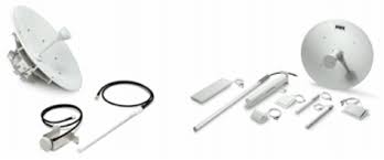
Here are some types of antennas:
This is an outdoor omidirectional antenna. I use this type to cover outdoor areas, but the AP is placed inside (budget)This is a yagi outdoor directional antenna, mostly used to connect to APs > buildings
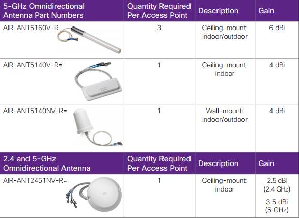
…and here is a wide range of antennas. There are many many more. Often you find something like this:
This is very helpful to get an overview, which antennas suitable for your use case.
Next we need to check the H- and E-plane and if this also fit’s, we’re done. But wait….H-plane is also called azimut and than called A-plane. Summarized H-plane aka A-plane and E-plane.
Watt is a energy measurement. 1 Watt for example. 1W = 1000mW, 1000W = 1 kW
Decibel on the other side measures a signal in comparison to a reference point, is it better (+) , is it worse (-) or still the same (0). -> 10 dB = the signal is 10x better (amplified) as measured at the reference point -> 0 dB= the received signal strength is equal to the reference point -> -10 dB = the signal strength is only 1/10
We mostly need to set dB in relation to mW, so that this looks like his: -> 10 dBm = 10mW -> 0 dBm = 1mW -> -10 dBm = 1/10mW
SOUNDs easy, but that’s not all. The time I worked as a Club-DJ several years ago, the first thing that get’s me into there was the technique of big sound-systems, aka PA. A important thing to keep there in mind was this: 3dB doubles the power the amplifier produces, 10dB doubles the audible sound.
It’s enough to remember 3dB is the double of power, -3dB is the half of power and things I’ve written above. This helps you out to overcome most situations, for exact calculations we need a calculator.
YEAH, let’s calculate some dBs to mW: I hope someone can follow me because it’s written fresh out of my brain 😀
EXAMPLE: 39dB -> You’re looking how often get „10“ into, it’s 3 times. Every time the 10 goes in it stands for a „0“ and because our reference point is 1mW we’re writing this down: 1000mW Now the 9dBs left, here we look out how often „3“ get’s in, for every match we double the previous result: 2000mW -> 4000mW -> 8000mW = 8 Watt
Ohhwee and mW to dBs: We’ve 2400mW. So first we figure out if: 10 goes in 2400mW -> YES = +10dBm 10 goes in 240mW -> YES = +10dBmm 10 goes in 24mW -> YES = +10dB 10 goes in 2,4mW -> NO
Then figure out how often 2 fit’s in and add 3dB for every hit: 2 fit’s in 2,4mW -> YES = 1x +3dBm
Let’s get a bit deeper into the SNR topic. The RSSI is the signal we want, like to listen to somebodys voice. The Noice Floor is the Interference we don’t want, like your crazy neighbor who is listen to music at maximum volume. To calculate the SNR we need to subtract the Interference from the RSSI.
A RSSI of „0“ would be the greatest thing ever and I’am trying for years to get this working, but with no success :D. Joke aside, a RSSI of „0“ is impossible. Let’s take the following as a guideline: RSSI -20 = great RSSI -50 = okay RSSI -70 = baaaaad
This is our case: RSSI -70 and noise is -95. The calculation is going this way -> -70 – -95 -> -70 + 95 -> SNR 25 A SNR of 20+ is what we need :).
In this part I try to describe the basics of Radio Frequency. If you design und debug WLAN network you need a basic overview how this works.
The basic, how every RF communication works, it’s an Electronic-Magnetic Field. It is send in Wave-Forms away from the device. Imagine a pond and you throw a stone into it, the wave are getting away from the point the stone hits the water, like the radio-waves of an AP. Also the situation while the waves are moving further and further we’re talking about the attenuation. This means the decrease of a signal while moving through the room, away from the sending point, the energy getting less and less.
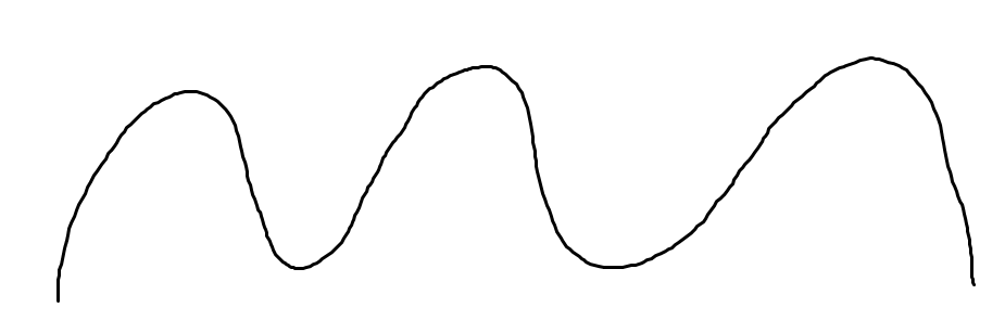
This how a simple waveform looks like:
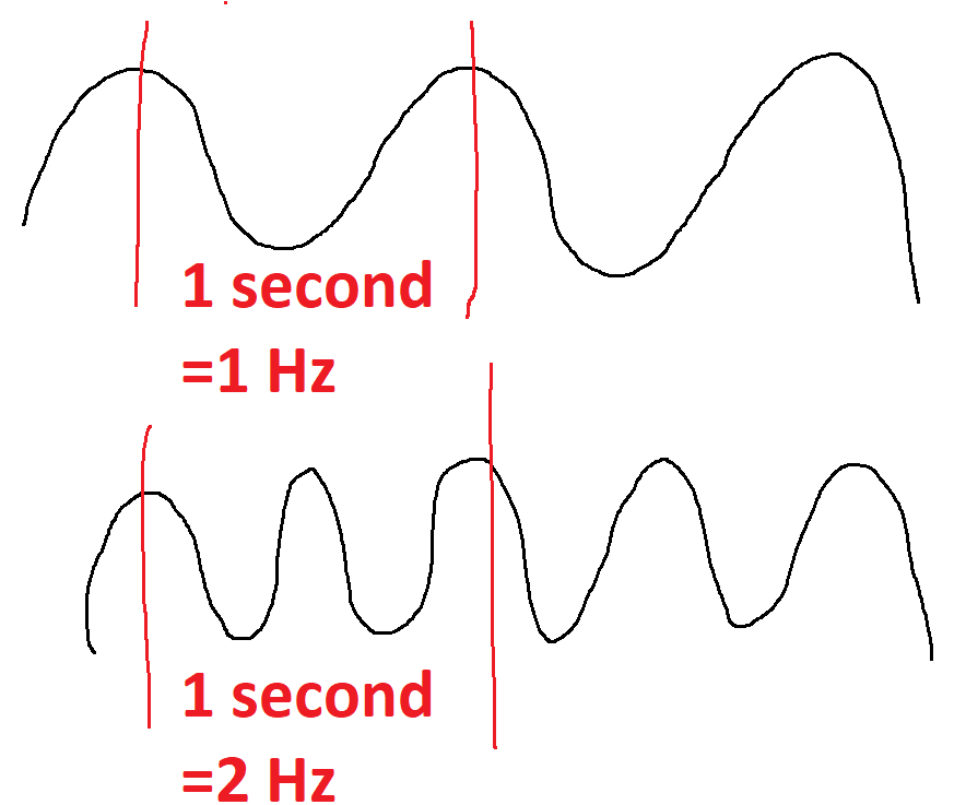
So what is the Frequency? A nice example is to measure how many times you can wave your hands in one second? I think two times should be okay :). The result are 2 Hertz/Hz and that’s it. The image below shows it, how many „wave’s“ the signal does in 1 second.
You see, the wavelength decides how many Hz are possible by a signal. The wavelength is also measurable if you measure he distance between peaks within a cycle. It’s important to remember: -> short wavelength = higher frequency, more cycles per second, short range -> long wavelength = lower frequency, less cycles per second, further range
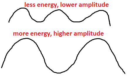
The Amplitude is the „height“ of the signal, example: If I throw a large rock into a pond the wave is getting higher rather than I throw a small rock. The waves are getting further, because of more energy. It simply looks like this:
RSSI – Received Singal Strentgh Indicator Now we now how the signal looks like but how could we measure it? The solution is the RSSI, the closer we get to 0, the better it is. With the RSSI we can decide how good a WLAN is received at out station
The wireless problems 🙂 – Path lost -> your RSSI is too low to remain connected, too far away from the AP – Scattering -> a foggy day an do this and it prevents the signal to get’s further – Lead -> very funny, because I’ve never seen this – at hospitals or power plants, okay but not in normal houses our buildings. But there can be other obstacles such as ferroconcrete walls or many other things that can absorb signal strength. – Reflections and multipathing are situations that are not unnormal. It’s simple the signal that arrives via different path at the receiver, because it’s getting reflected by obstacles. Because the signals arriving not at the same time, let’s say 180 degree, the UP of signal one is canceled out by the down of signal 2. If the signal is some degrees out of phase we call it „downfade“, is the signal in phase we call it „upfade“ -> stronger signal. – Noise is a big player in todays wireless networks. It’s the „sound“ of other individuals, talking at the same frequency as we do. This can be another WLAN or a device thats generating waves at this frequency we also use.
At least we can also measure the distance between the RSSI, that the indicator how good we receive the signal, and the noise, the interference. The result is the SNR, Signal to Noise Ratio. A lower value shows that the noise almost loud as we hear the signal we want to listen to. Imagine a music festival and of course this can is a noisy place. Your’re in front of the stage and trying to talk to a friend, that’s a hard job. Because the sound of the band, for example RAMMSTEIN^^ is sooooooo loud, your friend can’t understand anything. So the band makes the noise and you’re voice is the signal. Here the noise is so high that your signal is not being received. I hope this is helpful 😀
Every day we turn on our computer, connect with the wireless and are happy. This all works because of standards. The wireless network protocol stack and rules at layer 1 (physical layer, BITs) and layer 2 (data link, FRAMEs) are made by the IEEE. More precisely the 802.11 working-group is designing this standards and they’re downloadable but I’am still looking for the right link at https://standards.ieee.org, they changed something *grrr*
So the layer 1 and 2 basics and rules are in place but there must be an instance to check if the APs and wireless-NICs from different vendors are compatible with each other and with the IEEE rules and standards. This 3rd party is the „WIFI ALLIANCE„, they test the gear from the vendors out there.
A simple example, why a Regulatory Organization is needed, is if there are are two company’ss nearby, each with an active AP and both APs sending at the same frequency. The same as two colleagues are talking but each at the same time. The result is that is very hard to follow, now a person can talk louder so I can hear better but know the other person also talks louder and so an. But this is no way to handle this, there must be limits. This is the work of the Regulatory Organizations. The organize the usable frequencys and channels or the power rate that is allowed to use. There is the FCC in USA, the ETSI in Europe, the TELEC in Japan, in India the BRAI,…..